








Engineering

Project 06 / 06

Wind Turbine Generator for Power Generation

A small wind-driven generator was built around an 80-turn rotating coil, opposing neodymium magnets, and carbon-brush contacts. In a wind tunnel, open-circuit AC EMF was read from paused oscilloscope frames at five wind speeds, then compared with a simplified Faraday's-law model.

Physical build + reported open-circuit EMF
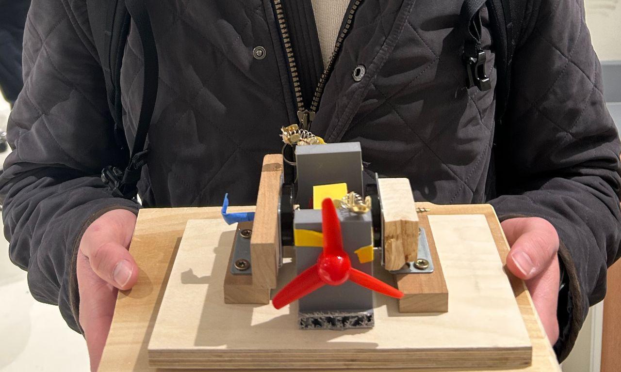
Physical generator — 80-turn rotating coilCompleted team-built generator: a propeller-driven shaft and coil rotate between opposing magnets on a wooden base with 3D-printed supports.
Completed small wind-driven generator on a wooden base with a red propeller, rotating coil, opposing neodymium magnets, 3D-printed supports, and brush contacts.
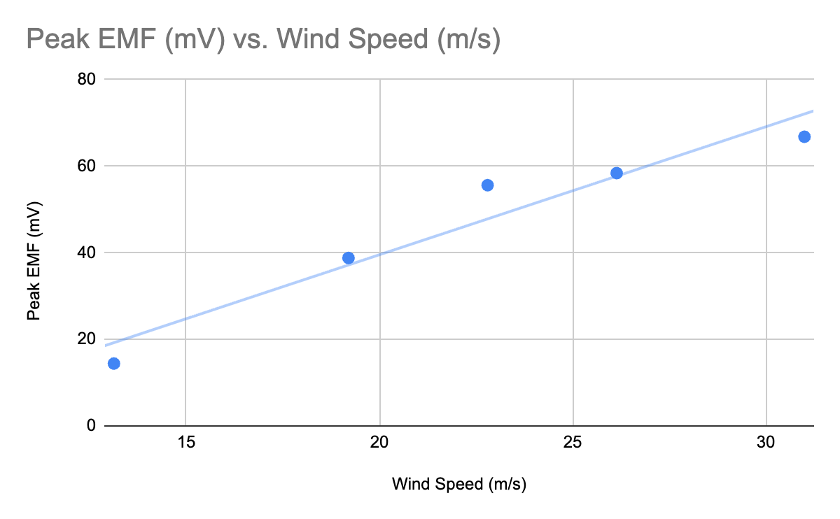
Five reported observations — 14.40 to 66.80 mVReported peak open-circuit EMF at five wind speeds. Wind speed is a proxy for rotation because turbine RPM was not recorded.
Measured plot of peak open-circuit EMF across five wind speeds, rising from 14.40 millivolts at 13.13 meters per second to 66.80 millivolts at 31.00 meters per second.

Reported peak open-circuit EMF increased across five observations, from 14.40 mV at 13.13 m/s to 66.80 mV at 31.00 m/s.

01From airflow to observable EMF

The engineering question was whether a wind-driven rotating coil could produce measurable induced voltage and support a bounded comparison with Faraday's law.
The team set out to design and fabricate a small generator, observe induced voltage at several wind speeds, examine the resulting waveforms, and compare the observations with a simplified Faraday's-law model. A propeller supplied the mechanical input; the project measured electrical potential at open circuit rather than delivered electrical power.

The recorded test variable was wind speed. Turbine RPM was not directly measured, so the evidence supports a five-point wind-speed/peak-EMF observation set rather than a calibrated relationship between rotation and generator output.

02Building the rotating generator

The physical design links airflow, rotation, changing magnetic flux, and a stationary measurement connection.

Mechanical-to-electrical path

The team wound an 80-turn copper coil around a custom 3D-printed PLA frame and mounted it on a 2 mm steel shaft. Two facing neodymium magnets, each approximately 3.2 cm in diameter, created the magnet-gap region around the rotating coil; the shaft was supported by two team-designed printed structures on a wooden base.

A plastic propeller attached to the shaft received wind-tunnel airflow. Carbon-brush contacts transferred the induced AC voltage from the rotating shaft to a Rigol DS1104Z oscilloscope, making the signal observable without claiming a loaded electrical output.

  • Propeller-driven steel shaft rotates the coil.
  • The 80-turn coil moves through the field between opposing magnets.
  • Carbon brushes connect the rotating assembly to stationary oscilloscope probes.

03Tuning the physical coupling

The final test configuration followed practical adjustments to the magnet gap, airflow orientation, and brush contact.

Initial testing used a 57 mm magnet spacing and produced weak output. The magnets were later spaced approximately 30 mm apart for the final configuration. The report treats the smaller gap as a practical way to increase flux linkage, but it does not provide a before-and-after voltage series that would quantify the change.

For wind-tunnel trials, the assembly was taped to the test platform and the propeller faced directly into the airflow. The report describes side-on and reverse orientations as visibly lower/negligible voltage conditions, while brush wear and contact variation required each trial to begin with a contact check and, when needed, brush repositioning.

04Five wind-tunnel observations

The primary quantitative evidence is a five-point record of reported peak open-circuit EMF at specified wind speeds.

Reported peak open-circuit EMF observations
TrialWind speedPeak EMF
113.13 m/s14.40 mV
219.20 m/s38.80 mV
322.80 m/s55.60 mV
426.14 m/s58.40 mV
531.00 m/s66.80 mV

At each reported wind speed, the propeller was allowed to reach steady rotation and the AC-coupled oscilloscope display was paused so its peak value could be read visually. Each row is one reported observation; no repeated-trial statistics or uncertainty bounds are documented. Wind speed is a proxy because RPM was not recorded.

Oscilloscope evidence

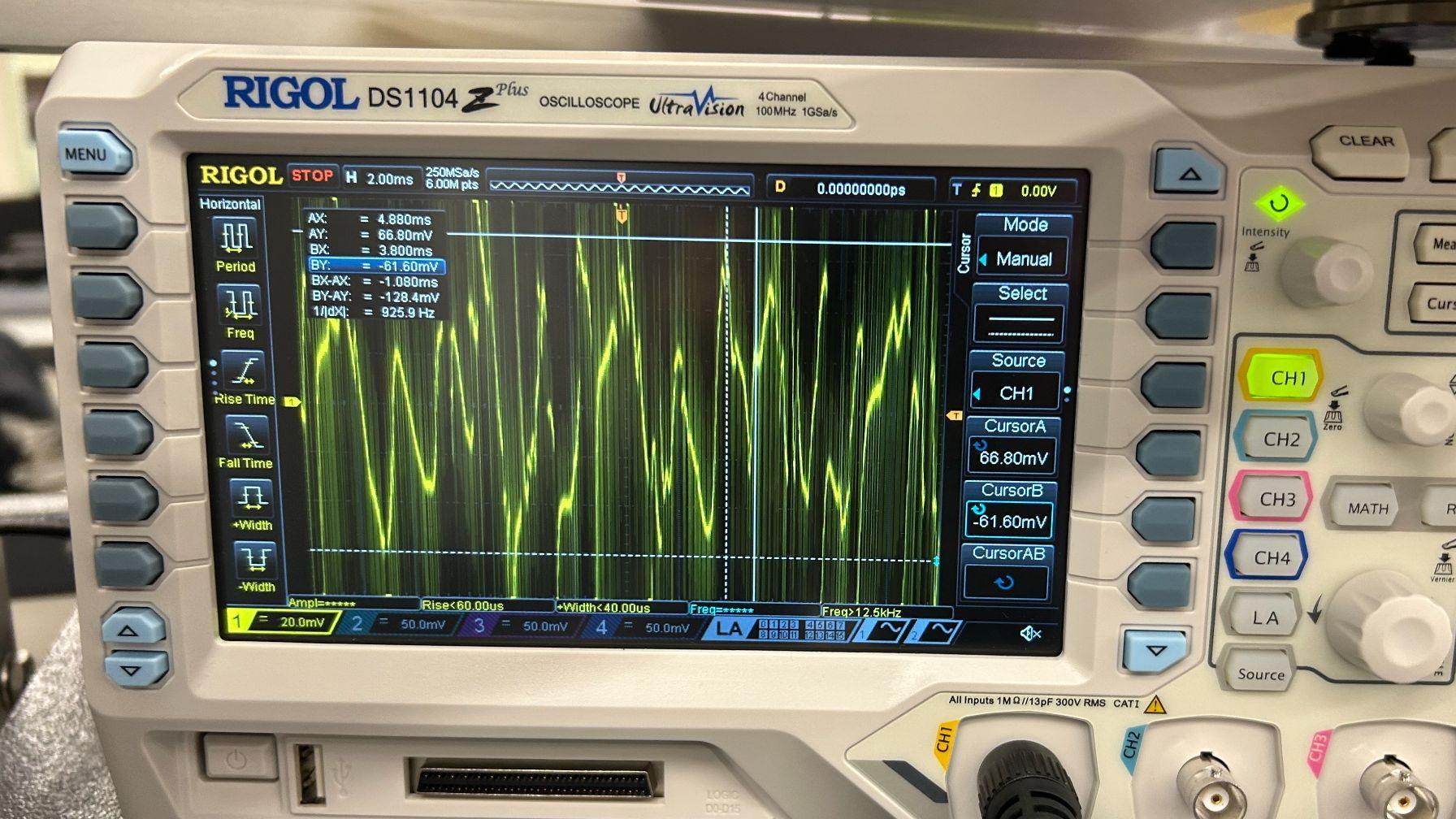
Rigol oscilloscope display showing a periodic, non-sinusoidal waveform measured from the wind-driven generator, with a 66.80 millivolt cursor reading visible on the screen.
AC-coupled Rigol DS1104Z — open-circuit measurementOscilloscope record from the generator test. The report describes periodic, non-sinusoidal peaks; the 66.80 mV cursor reading corresponds to the reported highest-wind-speed observation.

The waveform serves as instrumentation evidence of periodic induced voltage, not as an RPM, frequency, load, or power characterization.

Reported peak open-circuit EMF

14.40 mV at 13.13 m/s → 66.80 mV at 31.00 m/s

Across the five reported observations, peak EMF rose with wind speed. The evidence is a bounded set of paused-frame readings, not a calibrated generator-performance curve.

No load, current, power, efficiency, torque, direct RPM, repeatability, or uncertainty result is established by this table or waveform.

05Using Faraday's law as a bounded model

The report's equations explain the design concept while keeping estimated model inputs separate from the measured observations.

Rotating-coil induction model

Faraday's law relates induced EMF to changing magnetic flux. For the report's simplified rotating-coil model, turn count, effective field, coil area, and angular velocity set an idealized peak-EMF estimate.

Number of coil turns; the project used 80.
Effective magnetic field in the coil region; modeled rather than measured for the final configuration.
Coil area, reported as approximately 3.23 × 10⁻⁴ m².
Angular velocity; not directly recorded during the wind-tunnel observations.

The report used B_eff ≈ 0.03 T and ω ≈ 40–70 rad/s as model estimates, producing an illustrative 31–54 mV range. Neither quantity is a measured test result.

The source model used the 80-turn coil and reported coil area to estimate an order of magnitude for peak EMF. Its effective field value of approximately 0.03 T and angular-velocity range of approximately 40–70 rad/s were assumptions because no final Gauss-meter reading or direct RPM measurement was recorded.

The model therefore gives context for the observed voltage range rather than a calibrated prediction. It can support a conceptual link between changing flux and induced voltage without converting wind speed into a measured rotation rate or presenting the estimate as validation accuracy.

06What the test establishes—and what it does not

The defensible outcome is a small, team-built generator with observed open-circuit AC EMF—not a complete generator-performance characterization.

Defensible outcome

Measured open-circuit AC EMF

The shared team built and wind-tunnel-tested a rotating-coil generator that produced the five reported peak-EMF observations and a periodic non-sinusoidal waveform.

This does not establish delivered electrical power, efficiency, optimized performance, or commercial wind-turbine behavior.

Jack Brogan, Dylan Luebke, and Cooper Robillard are the report's three authors. The public role, Generator Design & Testing, communicates Cooper's documented workstream while preserving the report's shared construction, testing, analysis, and reporting attribution.

The report's next steps are to directly measure angular velocity and magnetic field strength, add a known electrical load, revise coil/magnet geometry, and improve brush or slip-ring contacts. These are proposed measurements and redesign directions, not completed results.