04

Counter-Flow Heat Exchanger CFD Analysis

Thermal analysis of a counter-flow shell-and-tube heat exchanger using ε-NTU calculations and ANSYS Fluent CFD to compare temperature, flow, and heat-transfer behavior at two inlet velocities.

Role
CFD & Thermal Analysis
Stack
ANSYS Fluent · CFD · ε-NTU · Heat Transfer · Thermal Analysis
View full project →

Two velocity cases — thermal / flow comparison

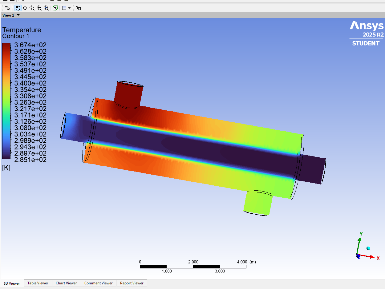
ANSYS Fluent full-range temperature contour for Case A at 0.5 meters per second, showing hot shell-side water and cold central tube-side water across the exchanger.
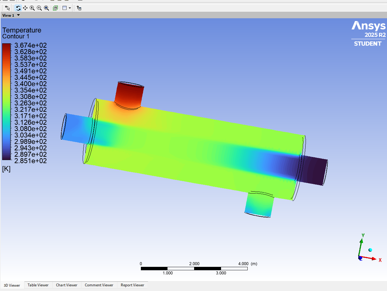
ANSYS Fluent full-range temperature contour for Case B at 0.05 meters per second, showing the larger temperature change associated with slower flow.
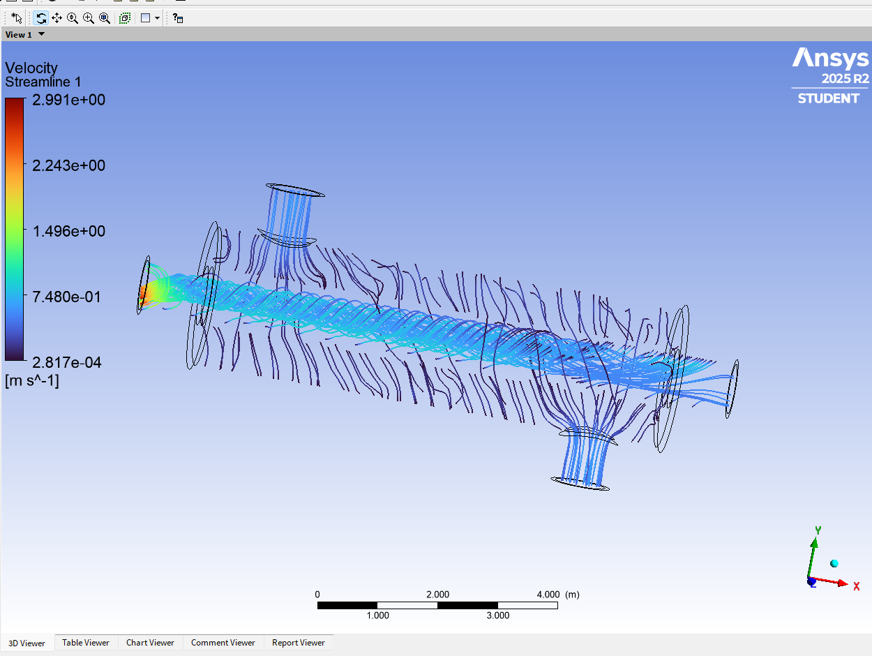
ANSYS Fluent velocity streamlines for Case A at 0.5 meters per second, showing direct tube-side flow and curved distributed shell-side flow.
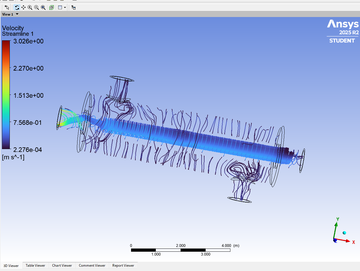
ANSYS Fluent velocity streamlines for Case B at 0.05 meters per second, showing direct tube-side flow and curved distributed shell-side flow.

Slower flow increases residence time and temperature change; faster flow produces the slightly higher theoretical heat-transfer rate through greater mass flow.

04

Counter-Flow Heat Exchanger CFD Analysis

Thermal analysis of a counter-flow shell-and-tube heat exchanger using ε-NTU calculations and ANSYS Fluent CFD to compare temperature, flow, and heat-transfer behavior at two inlet velocities.

Role
CFD & Thermal Analysis
Stack
ANSYS Fluent · CFD · ε-NTU · Heat Transfer · Thermal Analysis
View full project →

Two velocity cases — thermal / flow comparison

ANSYS Fluent full-range temperature contour for Case A at 0.5 meters per second, showing hot shell-side water and cold central tube-side water across the exchanger.
ANSYS Fluent full-range temperature contour for Case B at 0.05 meters per second, showing the larger temperature change associated with slower flow.
ANSYS Fluent velocity streamlines for Case A at 0.5 meters per second, showing direct tube-side flow and curved distributed shell-side flow.
ANSYS Fluent velocity streamlines for Case B at 0.05 meters per second, showing direct tube-side flow and curved distributed shell-side flow.

Slower flow increases residence time and temperature change; faster flow produces the slightly higher theoretical heat-transfer rate through greater mass flow.